![]()
![]()
![]()
![]()
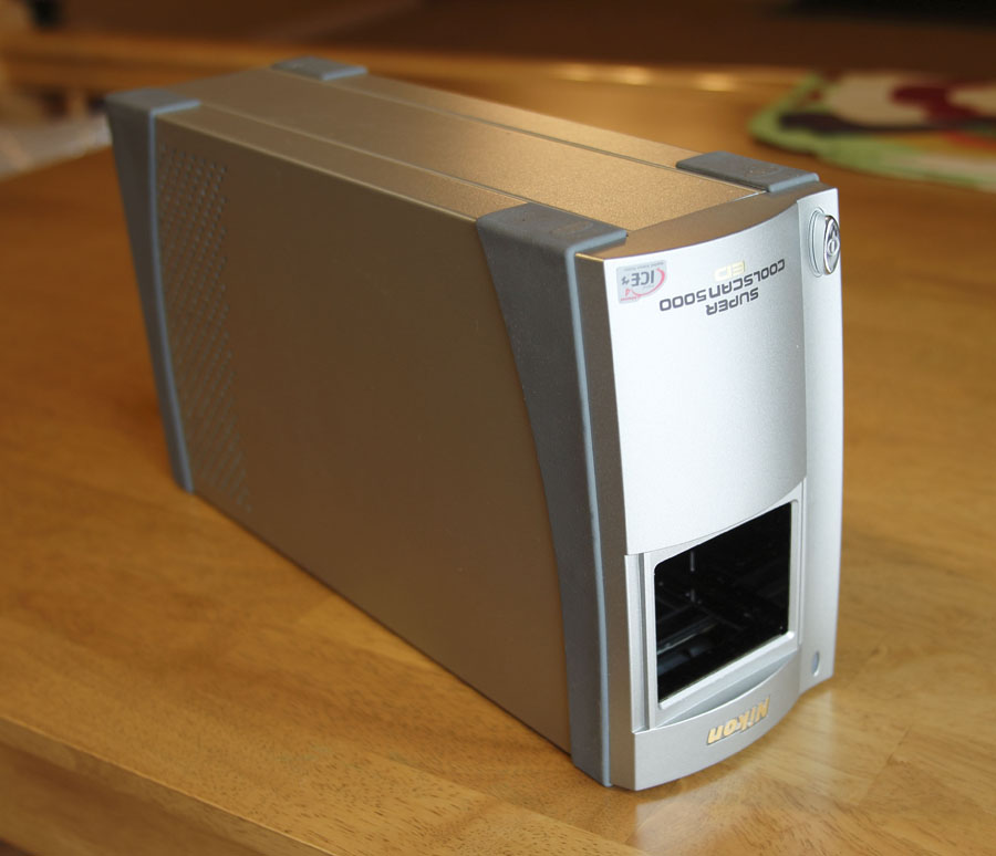
Disassembly of Nikon Super Coolscan LS-5000 scanners (and some repair suggestions)
Disassembly are shown here for LS-5000.
1) Unplug the power & USB cable and remove adaptors. Set the scanner upside down on a clean area. Set it upside down if you are planning to inspect/clean the mirror.
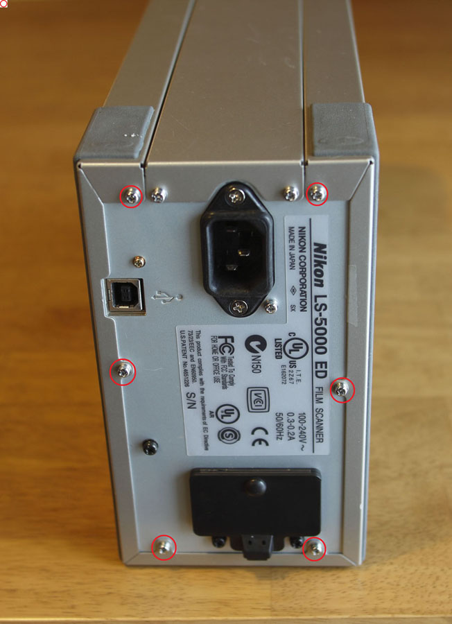
2) Remove these 6 screws on the back of the unit.
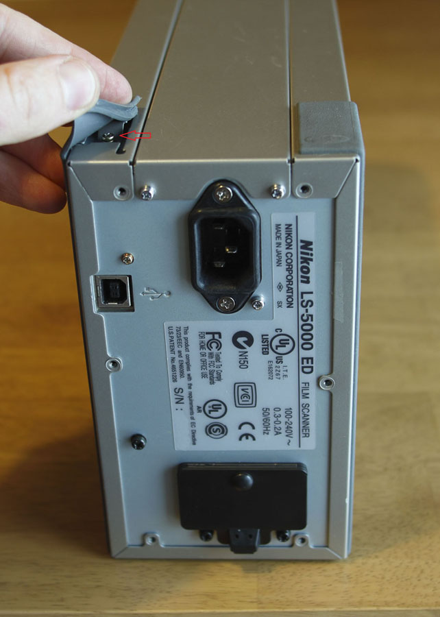
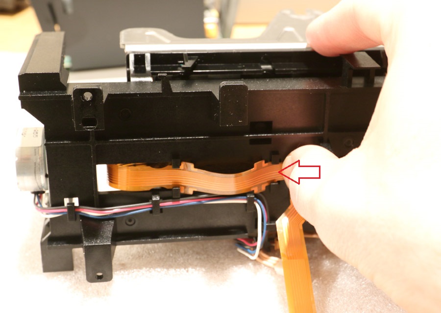
3) Pull out the rubber pads as shown by a red arrow above. There are 4 pads in the corners on the bottom of the scanner, and they cover 4 screws. Remove these 4 screws and slide the metal shell off.
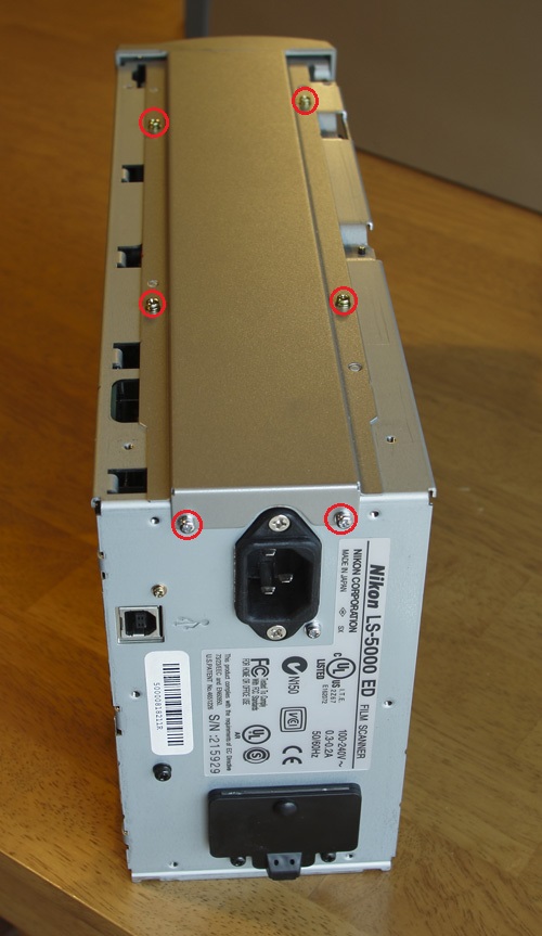
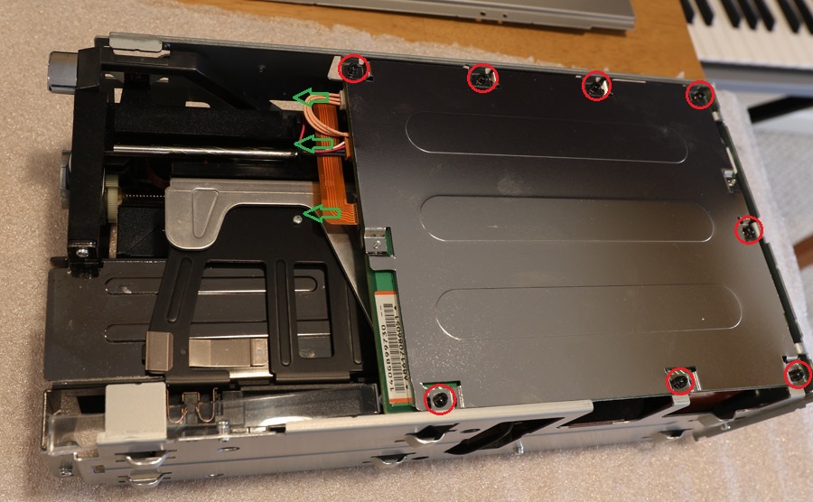
4) Remove the 6 screws indicated by red circles. Remove the bottom panel.
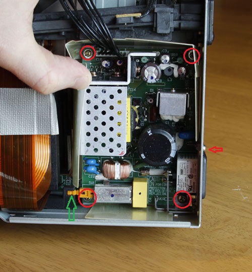
5) Remove these 5 screws (4 circled and one on the back panel - red arrow above is pointing at it). Unplug the black 8-lead cable connecting the power supply to the main board and lift the power supply out. First disconnect it from the plastic power arm at a point indicated by a green arrow - just pull that side power supply up while holding the black side with a screwdriver. After that remove the plastic isolation cage out as well.
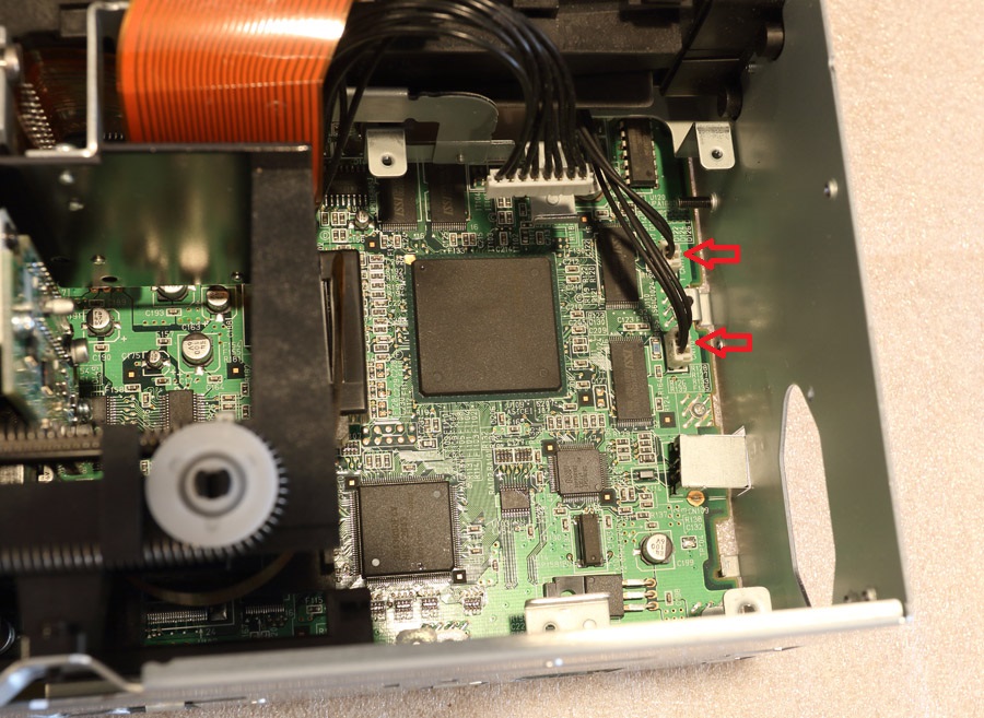
6) With power supply and plastic cage out, you can see the back of the main board cables connected to it. You will need to disconnect the two cables indicated by red arrows by gently pulling and wiggling the wires.
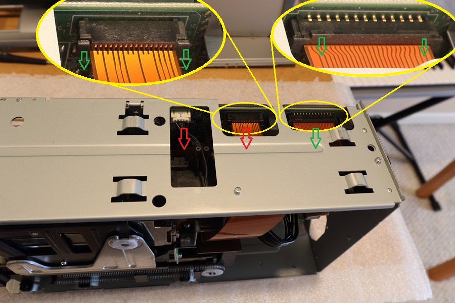
7) Also disconnect the three cables by pulling them in the directions of red arrows. The flex cables are held by pressure brackets. First, release the brackets by pulling the plastic tabs in the direction indicated by the green arrows. Then the flex cables will come out easily. You never need to apply much force with flex cables - and make sure you do do not!
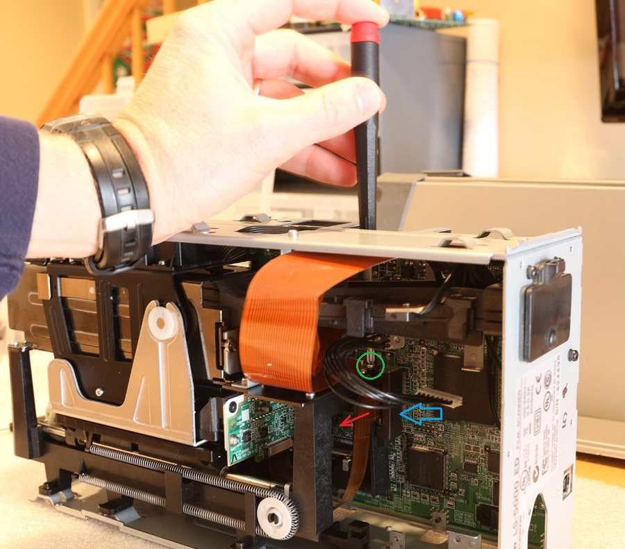
8) Now the tricky part. There is one more flex cable connected to the center of the main board, as shown above. First, remove the screw holding a shroud around the ferrite bead. Then pull the plastic tab of the pressure bracket in the direction indicated by the red arrow. Then the flex cable will come out easily. Again, never apply force to pull flex cables!
9) Disconnect these three cables (one of then is flex).
Then remove 8 black screws on the back of the main board. Take the main board out.
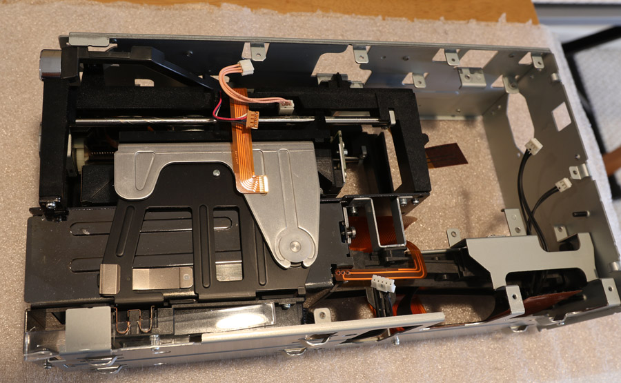
10) This is the rest of the scanner at this point.
11) Remove these 4 screws and take the top bracket off .
12) The big black part labeled PC-GF20 is the LED source. This parts sometimes fails. The good news is that the same part is used for LS-40 (aka IV), LS-4000, LS-50 (aka V), and LS-5000. So you can buy used LS-40 on e-bay and have a fairly inexpensive replacement part. The bad news for LS-4000 owners is that you have to disassemble it this far to get to the LED source. Nikon modified the design for LS-5000 so you do not need to go nearly this far in disassembly to be able to replace the LED source.
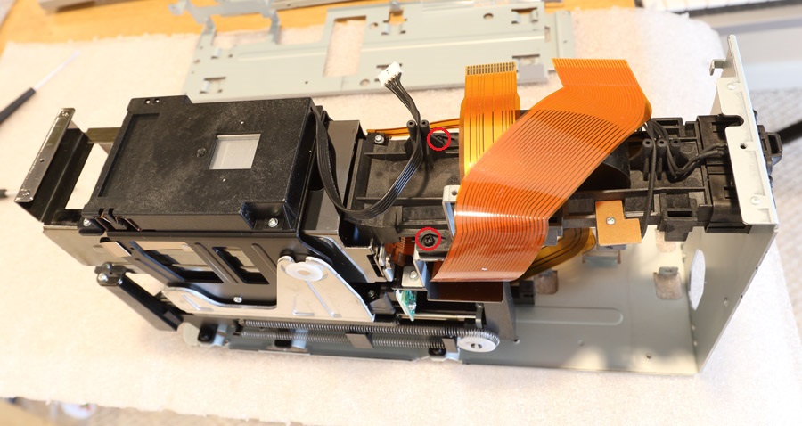
If you are repairing the scan head gears, proceed by removing the two black screws above and taking the film conduit out.
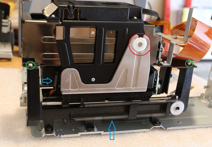
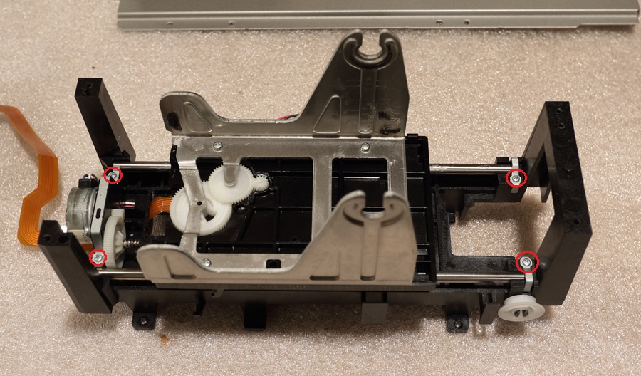
13) Remove the two springs (indicated by blue arrows). Remove 4 screws (2 are indicated by the red arrows, two more on the back - cannot be seen in this photo). Remove two white plastic clips (one is indicated by a green circle, the other one is on the back) holding the carriage.
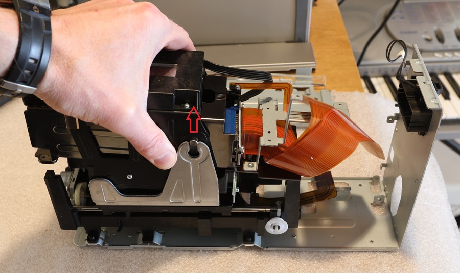
14) Gently pull the scan transport up. Careful to feed the flex cables to make sure they do not get damaged.
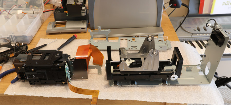
15) Set the scan transport aside.
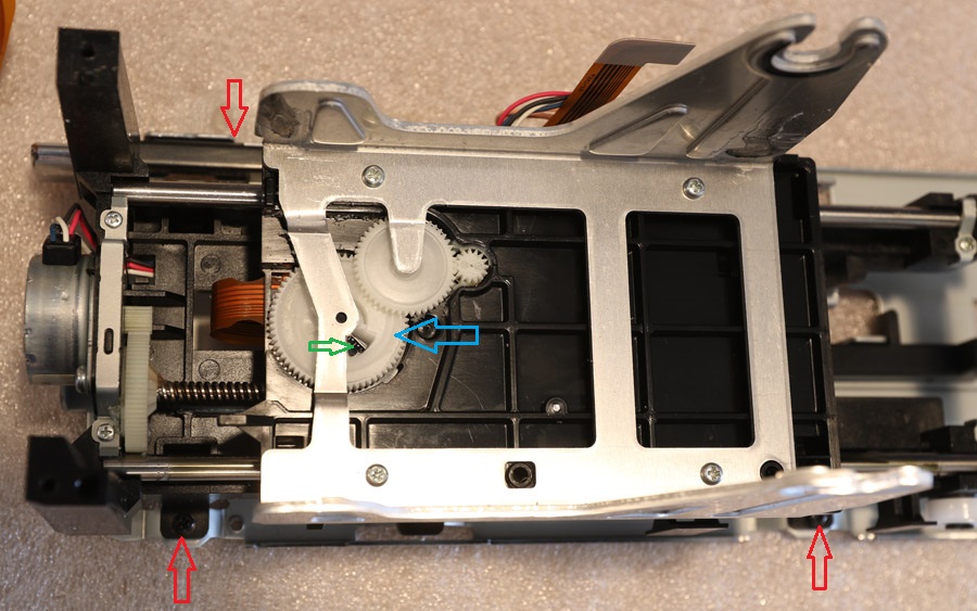
16) The autofocus mechanism is in the center. The gear that pushed the scan head up and down has radial incline which pushes up the plastic pin in the scan head. One of the potential problems - you can see this gear has a groove (indicated by blue arrow) worn out by that plastic pin. In the extreme cases the autofocus stops working. The other problem - the proximity sensor (it can be seen in the opening indicated by a green arrow). The proximity sensor may fail (there is an LED there that may fail), or this opening may get obstructed by debris. In both cases autofocus will stop working properly, and the scanner will report a failure during initialization, see here. If you are lucky - you may just have to clean the sensor opening by blowing air at it. If not - you will need to replace the autofocus sensor or entire motor-sensor assembly.
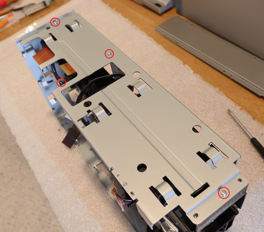
To proceed with disassembly, first remove three black screws indicated by red arrows and disconnect the top part of the chassis.
17) Push the flex cable as shown above to release it from the tabs holding it.
17) Almost there! Remove 4 screws and lift the carriage with the guide rods.
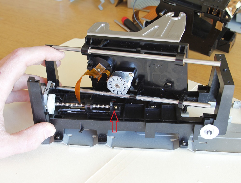
18) Now you can see the worm drive mechanism (this is a photo of LS-4000, LS-5000 has slightly different leadscrew). As you can see, the leadscrew is held on one side (near the front of the scanner) by the steel plate. the back side should be held by a plastic part, which is missing here (place indicated by a red arrow). The good news is that the same part is used for LS-40 (aka IV), LS-4000, LS-50 (aka V), and LS-5000.
Update. I have taken accurate measurements of both back
support and worm gear slider for these scanners and had them printed on a 3D
printer. Write to me if you need them at
![]() .
.
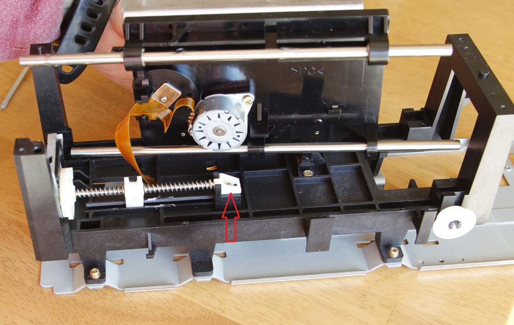
19) The picture above shows the same mechanism for LS-40. You can immediately see that the worm screw has a different pitch. But the plastic back support is the same. Take it out and use it to repair your LS-4000 or LS-5000! Reassemble in the reverse order.
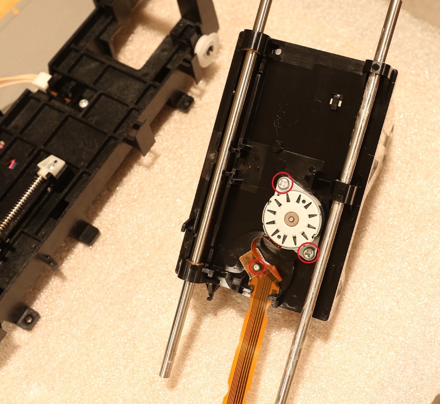
20) The picture above shows the autofocus motor and sensor. In order to replace them take three screws out.