![]()
![]()
![]()
![]()
Failed USB communication repair in Nikon Super Coolscan LS-50 (V) and LS-5000
This seems to be a relatively common failure mode of Nikon Coolscan LS-50 (V) and LS-5000 ED scanners. The typical symptom is that scanner passes power-up initialization fine (no fast blinking), but is not recognized by a computer (in Windows - Device Manager does not see it). The scan software reports that it cannot find a scanner.
I had long been stymied by USB communication failures in Nikon LS-50 (V) and LS-5000 scanners. I initially thought that the ESD probably kills USB controller ISP1581BD. But replacing it did not fix the problem...
Graeme Hardie at LincolnScan in UK (https://lincolnscan.co.uk/Coolscan.html) investigated this and came up with a work-around. So far every LS-50 or LS-5000 motherboard that came to me with USB communication failure came back to life after a repair per Graeme's recipe.
Disassembly and repair are fairly modest.
Here is Graeme's reasoning:
USB Vbus input on Nikon LS-50 and LS-5000 devices is connected directly to EI-107 ASIC VBUSIN port. With capacitor and varistor disconnected from this input, approx 5Mohm (ie std CMOS input) should be measured to ground (probe with -ve terminal). If it measures open circuit or the value is significantly non-5MOHm then the input is damaged.
The purpose of VBUSIN is to detect that host is ON since USB2.0 (7.2.1), spec says:
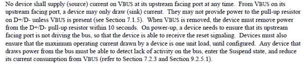
And also see:
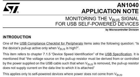
There is an output from EI-107 ASIC called VBUSINT whose state changes with USB connection/disconnection. Is this a mirror of VBUSIN?
In LS-50 schematic, VBUSINT runs to MCU H8/3003 pin 101 (P81/CS3bar/IRQ1bar) and nowhere else.
In LS-5000, Graeme Hardie deduced that VBUSINT runs to MCU H8S/2643 pin 108 (PF0/BREQbar/IRQ2bar).
Voltage spikes probably damage EI-107 ASIC VBUSIN port. But if its only function is to pass that (TTL) signal to corresponding pin of the MCU H8 or, MCU H8S, then tying that pin to +3.3V (via 10 resistor) should trick the scanner into thinking that it is connected to the computer, and make it communicate.
So here is the procedure.
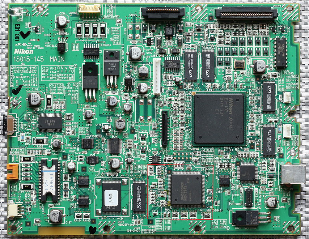
1. Follow steps 1) through 9) in LS-5000 disassembly procedure. Then, if necessary, remove the screws holding the metal PCB shields to expose the motherboard.
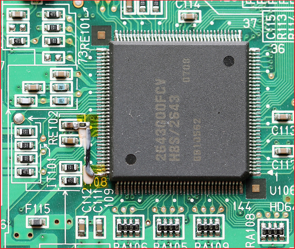
2. For LS-5000 board: lift MCU H8/3003 pin 108 and tie lifted pin to 3.3V (for example on the right side of C118) through a 10k resistor, see below:
a zoom of the area inside red box showing the repair on LS-5000 motherboard:
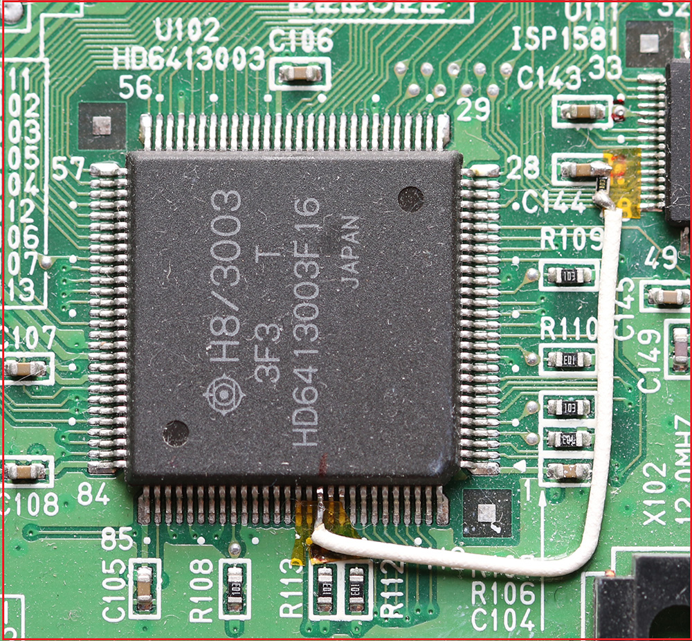
3. For LS-50, the closest place I found to pick 3.3V from is on the right side of C144 (left side of a large capacitor C134) also works:
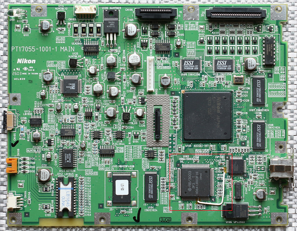
a zoom of the area inside red box showing the repair on LS-50 motherboard:
Good luck!